The Label Distribution Protocol (LDP) is a protocol for distributing labels in non-traffic-engineered applications. LDP allows routers to establish label-switched paths (LSPs) through a network by mapping network-layer routing information directly to data link layer-switched paths.
These LSPs might have an endpoint at a directly attached neighbor (comparable to IP hop-by-hop forwarding), or at a network egress node, enabling switching through all intermediary nodes. LSPs established by LDP can also traverse traffic-engineered LSPs created by RSVP.
LDP associates a forwarding equivalence class (FEC) with each LSP it creates. The FEC associated with an LSP specifies which packets are mapped to that LSP. LSPs are extended through a network as each router chooses the label advertised by the next hop for the FEC and splices it to the label it advertises to all other routers. This process forms a tree of LSPs that converge on the egress router.
LDP is a signaling protocol that runs on a device configured for MPLS support. The successful configuration of both MPLS and LDP initiates the exchange of TCP packets across the LDP interfaces. The packets establish TCP-based LDP sessions for the exchange of MPLS information within the network. Enabling both MPLS and LDP on the appropriate interfaces is sufficient to establish LSPs.
LDP is a simple, fast-acting signaling protocol that automatically establishes LSP adjacencies within an MPLS network. Routers then share LSP updates such as hello packets and LSP advertisements across the adjacencies. Because LDP runs on top of an IGP such as IS-IS or OSPF, you must configure LDP and the IGP on the same set of interfaces. After both are configured, LDP begins transmitting and receiving LDP messages through all LDP-enabled interfaces. Because of LDP's simplicity, it cannot perform the true traffic engineering which RSVP can perform. LDP does not support bandwidth reservation or traffic constraints.
When you configure LDP on a (LSR), the router begins sending LDP discovery messages out all LDP-enabled interfaces. When an adjacent LSR receives LDP discovery messages, it establishes an underlying TCP session. An LDP session is then created on top of the TCP session. The TCP three-way handshake ensures that the LDP session has bidirectional connectivity. After they establish the LDP session, the LDP neighbors maintain, and terminate, the session by exchanging messages. LDP advertisement messages allow LSRs to exchange label information to determine the next hops within a particular LSP. Any topology changes, such as a router failure, generate LDP notifications that can terminate the LDP session or generate additional LDP advertisements to propagate an LSP change.
Starting in Junos OS Release 20.3R1, support for MPLS to provide LDP signaling protocol configuration with the control plane functionality.
This example shows how to create and configure LDP instances within an MPLS network.
Before you begin:
Note: Because LDP runs on top of an IGP such as IS-IS or OSPF, you must configure LDP and the IGP on the same set of interfaces.
To configure LDP-signaled LSPs, you must enable the MPLS family on all transit interfaces in the MPLS network and include all the transit interfaces under the [ protocols mpls ] and [ protocols ldp ] hierarchy levels.
In this example, you enable the MPLS family and create an LDP instance on all the transit interfaces. Additionally, you enable the MPLS process on all the transit interfaces in the MPLS network. In this example, you configure a sample network as shown in Figure 1.
Figure 1: Typical LDP-Signaled LSPTo quickly configure this example, copy the following commands, paste them into a text file, remove any line breaks, change any details necessary to match your network configuration, copy and paste the commands into the CLI at the [edit] hierarchy level and then enter commit from configuration mode.
R1
set interfaces ge-0/0/0 unit 0 family mpls set protocols mpls ge-0/0/0 unit 0 set protocols ldp interface ge-0/0/0 unit 0
R2
set interfaces ge-0/0/0 unit 0 family mpls set protocols mpls ge-0/0/0 unit 0 set protocols ldp interface ge-0/0/0 unit 0 set interfaces ge-0/0/1 unit 0 family mpls set protocols mpls ge-0/0/1 unit 0 set protocols ldp interface ge-0/0/1 unit 0
R3
set interfaces ge-0/0/0 unit 0 family mpls set protocols mpls ge-0/0/0 unit 0 set protocols ldp interface ge-0/0/0 unit 0
To enable LDP instances within an MPLS network:
[edit] user@R1# set interfaces ge-0/0/0 unit 0 family mpls
[edit] user@R1# set protocols mpls interface ge-0/0/0 unit 0
[edit] user@R1# set protocols ldp interface ge-0/0/0 unit 0
Confirm your configuration by entering the show command from configuration mode. If the output does not display the intended configuration, repeat the configuration instructions in this example to correct it.
For brevity, this show output includes only the configuration that is relevant to this example. Any other configuration on the system has been replaced with ellipses (. ).
user@R1# show . interfaces < ge-0/0/0 < unit 0 < family inet < address 10.100.37.20/24; >family mpls; > > > . protocols < mpls < interface all; >ldp < interface ge-0/0/0.0; >>
If you are done configuring the device, enter the commit command from the configuration mode to activate the configuration.
The Junos OS implementation of LDP supports LDP version 1. The Junos OS supports a simple mechanism for tunneling between routers in an interior gateway protocol (IGP), to eliminate the required distribution of external routes within the core. The Junos OS allows an MPLS tunnel next hop to all egress routers in the network, with only an IGP running in the core to distribute routes to egress routers. Edge routers run BGP but do not distribute external routes to the core. Instead, the recursive route lookup at the edge resolves to an LSP switched to the egress router. No external routes are necessary on the transit LDP routers.
You must configure LDP for each interface on which you want LDP to run. LDP creates LSP trees rooted at each egress router for the router ID address that is the subsequent BGP next hop. The ingress point is at every router running LDP. This process provides an inet.3 route to every egress router. If BGP is running, it will attempt to resolve next hops by using the inet.3 table first, which binds most, if not all, of the BGP routes to MPLS tunnel next hops.
Two adjacent routers running LDP become neighbors. If the two routers are connected by more than one interface, they become neighbors on each interface. When LDP routers become neighbors, they establish an LDP session to exchange label information. If per-router labels are in use on both routers, only one LDP session is established between them, even if they are neighbors on multiple interfaces. For this reason, an LDP session is not related to a particular interface.
LDP operates in conjunction with a unicast routing protocol. LDP installs LSPs only when both LDP and the routing protocol are enabled. For this reason, you must enable both LDP and the routing protocol on the same set of interfaces. If this is not done, LSPs might not be established between each egress router and all ingress routers, which might result in loss of BGP-routed traffic.
You can apply policy filters to labels received from and distributed to other routers through LDP. Policy filters provide you with a mechanism to control the establishment of LSPs.
For LDP to run on an interface, MPLS must be enabled on a on that interface. For more information, see the Logical Interfaces.
LDP uses the message types described in the following sections to establish and remove mappings and to report errors. All LDP messages have a common structure that uses a type, length, and value (TLV) encoding scheme.
Discovery messages announce and maintain the presence of a router in a network. Routers indicate their presence in a network by sending hello messages periodically. Hello messages are transmitted as UDP packets to the LDP port at the group multicast address for all routers on the subnet.
LDP uses the following discovery procedures:
Session messages establish, maintain, and terminate sessions between LDP peers. When a router establishes a session with another router learned through the hello message, it uses the LDP initialization procedure over TCP transport. When the initialization procedure is completed successfully, the two routers are LDP peers and can exchange advertisement messages.
Advertisement messages create, change, and delete label mappings for forwarding equivalence classes (FECs). Requesting a label or advertising a label mapping to a peer is a decision made by the local router. In general, the router requests a label mapping from a neighboring router when it needs one and advertises a label mapping to a neighboring router when it wants the neighbor to use a label.
Notification messages provide advisory information and signal error information. LDP sends notification messages to report errors and other events of interest. There are two kinds of LDP notification messages:
You can tunnel LDP LSPs over RSVP LSPs. The following sections describe how tunneling of LDP LSPs in RSVP LSPs works:
If you are using RSVP for traffic engineering, you can run LDP simultaneously to eliminate the distribution of external routes in the core. The LSPs established by LDP are tunneled through the LSPs established by RSVP. LDP effectively treats the traffic-engineered LSPs as single hops.
When you configure the router to run LDP across RSVP-established LSPs, LDP automatically establishes sessions with the router at the other end of the LSP. LDP control packets are routed hop-by-hop, rather than carried through the LSP. This routing allows you to use simplex (one-way) traffic-engineered LSPs. Traffic in the opposite direction flows through LDP-established LSPs that follow unicast routing rather than through traffic-engineered tunnels.
If you configure LDP over RSVP LSPs, you can still configure multiple OSPF areas and IS-IS levels in the traffic engineered core and in the surrounding LDP cloud.
Beginning with Junos OS Release 15.1, multi-instance support is extended to LDP over RSVP tunneling for a virtual router routing instance. This allows splitting of a single routing and MPLS domain into multiple domains so that each domain can be scaled independently. BGP labeled unicast can be used to stitch these domains for service forwarding equivalence classes (FECs). Each domain uses intra-domain LDP-over-RSVP LSP for MPLS forwarding.
With the introduction of the multi-instance support for LDP-over-RSVP LSPs, you cannot enable MPLS on an interface that is already assigned to another routing instance. Adding an interface that is part of another routing instance at the [edit protocols mpls] hierarchy level, throws a configuration error at the time of commit.
Tunneling LDP LSPs in RSVP LSPs provides the following benefits:
Learn about the benefits and get an overview of tunneling LDP over SR-TE.
It’s common for service providers to use the LDP signaling protocol with MPLS transport at the edges of their networks. LDP offers the advantage of being simple, but LDP lacks traffic engineering (TE) and sophisticated path repair capabilities that are often desired in the network’s core. Many service providers are migrating from RSVP to segment routing traffic engineering (SR-TE) in the core. SR-TE is also referred to as source routing in packet networks (SPRING).
It’s possible that the routers running LDP at the edge may not support SR capabilities. The service provider may wish to continue using LDP on these routers to avoid the need for an upgrade. In such scenarios, the LDP over SR-TE tunneling feature provides the ability to integrate routers that are not SR capable (running LDP) with routers that are SR capable (running SR-TE).
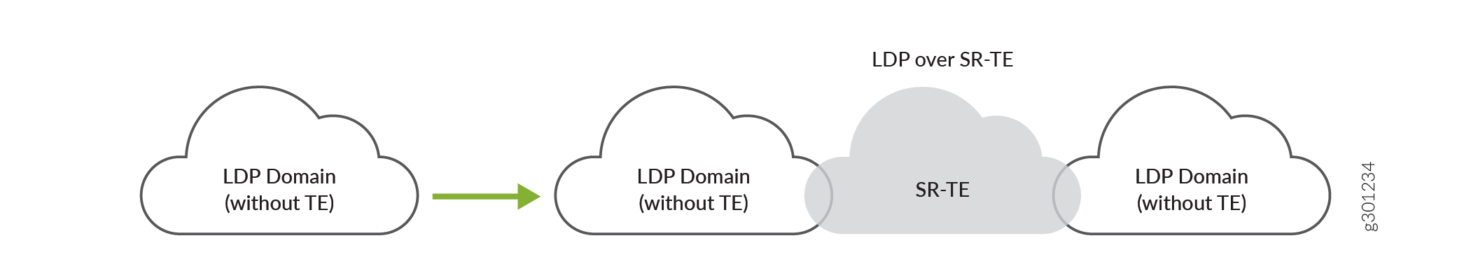
The LDP LSPs are tunneled through the SR-TE network, enabling interworking of LDP LSPs with SR-TE LSPs. For example, if you have LDP domains on the provider edge network and SR-TE in the core network, then you can connect the LDP domains over SR-TE, as shown in Figure 2.
Tunneling LDP over SR-TE supports co-existence of both LDP LSPs and SR-TE LSPs.
Figure 2: Interconnect LDP Domains over SR-TE in the Core Network
You can also tunnel LDP over SR-TE between LDP domains connected to inter-region core networks. For example, if you have multiple regional LDP domains connected to the inter-region SR-TE core networks, you can tunnel LDP across the inter-region SR-TE core network, as shown in Figure 3.
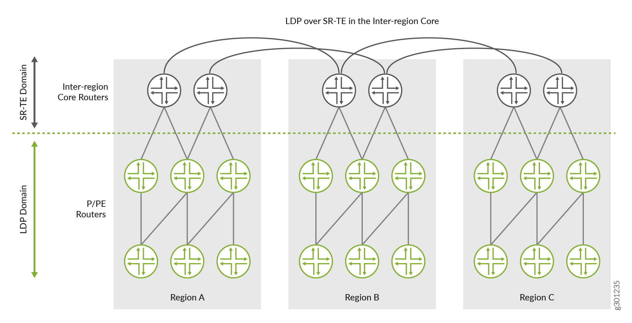
Figure 3: LDP over SR-TE between Inter-region Core Networks
In Figure 3, you have three regional networks (A, B, and C) running LDP. These regional LDP domains are connected to their respective regional core networks running SR-TE. The regional SR-TE core networks are further interconnected to other regional SR-TE core networks (inter-region core network). You can tunnel LDP over these inter-region SR-TE core networks and deploy services, such as Layer 3 VPNs, seamlessly. This scenario could be used in a mobile backhaul network, where the core aggregation layer runs LDP tunneled over SR-TE while the access layer runs LDP only.
To enable LDP tunneling over SR-TE in IS-IS networks, you need to configure the following configuration statements:
To enable LDP tunneling over SR-TE in OSPF networks, you need to configure the following configuration statements:
You can configure more than one tunnel source protocol for IGPs (IS-IS and OSPF) to create shortcut routes. When more than one tunnel source protocol is configured and if the tunnels from more than one protocol are available to a destination, the tunnel with the most preferred route is established. For example, if the core network has both RSVP LSPs and SR-TE LSPs and LDP tunneling is enabled for both RSVP and SR-TE LSPs, then the tunnel-source-protocol configuration selects the tunnel based on the preference value. The tunnel with the lowest preference value is most preferred. You can override this route preference with a specific protocol for all destinations by configuring the preference value, as shown in the following example:
[edit] user@host#set protocols isis traffic-engineering tunnel-source-protocol spring-te preference 2 user@host#set protocols isis traffic-engineering tunnel-source-protocol rsvp preference 5
[edit] user@host#set protocols ospf traffic-engineering tunnel-source-protocol spring-te preference 2 user@host#set protocols ospf traffic-engineering tunnel-source-protocol rsvp preference 5
In this example, you can see the preference value configured for the SR-TE tunnel source protocol is 2 and the preference value for RSVP tunnel source protocol is 5. In this case, the SR-TE tunnel are preferred because they have the lowest preference value as compared to RSVP tunnel source protocol.
It is not mandatory to configure the tunnel source protocol preference value. If more than one tunnel source protocol has the same preference value, then the tunnel is established based on the preferred route to the destination.
The targeted LDP session is established and is triggered when the SR-TE LSP comes up. The LSP session remains established until the LDP tunneling ( ldp-tunneling ) configuration is removed, or the SR-TE LSP is removed from the configuration.
Junos OS currently does not support LDP over colored SR-TE LSPs.
Use this example to learn how to tunnel LDP LSPs over SR-TE in your core network.
Our content testing team has validated and updated this example.
This example uses the following hardware and software components:
Are you interested in getting hands-on experience on this feature?
Visit Juniper vLabs to reserve your pre-configured vLab Sandbox: Segment Routing - Basic and try it out for free!
The following topology (Figure 4) shows two LDP domains (LDP Domain A and LDP Domain B) connected to the SR-TE core network, which extends the LSP session over the core by tunneling them over SR-TE.
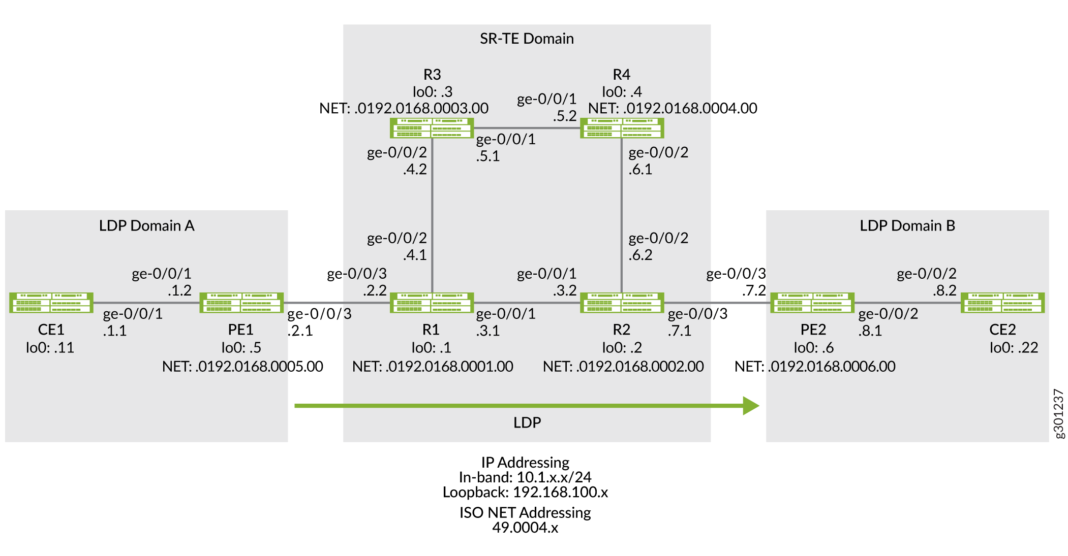
Figure 4: Tunneling LDP over SR-TE in the Core Network
To tunnel LDP LSP over SR-TE in your core network, perform these tasks:
To quickly configure this example, copy the following commands, paste them into a text file, remove any line breaks, change any details necessary to match your network configuration, copy and paste the commands into the CLI at the [edit] hierarchy level, and then enter commit from configuration mode.
Device CE1
set chassis network-services enhanced-ip set interfaces ge-0/0/1 description CE1-to-PE1 set interfaces ge-0/0/1 unit 0 family inet address 10.1.1.1/24 set interfaces lo0 unit 0 family inet address 192.168.100.11/32 set protocols ospf area 0.0.0.0 interface ge-0/0/1.0 set protocols ospf area 0.0.0.0 interface lo0.0 passive set routing-options router-id 192.168.100.11
Device PE1
set chassis network-services enhanced-ip set interfaces ge-0/0/1 description PE1-to-CE1 set interfaces ge-0/0/1 unit 0 family inet address 10.1.1.2/24 set interfaces ge-0/0/1 unit 0 family iso set interfaces ge-0/0/3 description PE1-to-R1 set interfaces ge-0/0/3 unit 0 family inet address 10.1.2.1/24 set interfaces ge-0/0/3 unit 0 family iso set interfaces ge-0/0/3 unit 0 family mpls set interfaces lo0 unit 0 family inet address 192.168.100.5/32 set interfaces lo0 unit 0 family iso address 49.0004.0192.0168.0005.00 set interfaces lo0 unit 0 family mpls set policy-options policy-statement export_bgp term a from protocol bgp set policy-options policy-statement export_bgp term a from protocol direct set policy-options policy-statement export_bgp term a then accept set routing-instances CE1_vpn1 instance-type vrf set routing-instances CE1_vpn1 protocols ospf area 0.0.0.0 interface ge-0/0/1.0 set routing-instances CE1_vpn1 protocols ospf export export_bgp set routing-instances CE1_vpn1 interface ge-0/0/1.0 set routing-instances CE1_vpn1 route-distinguisher 192.168.100.5:1 set routing-instances CE1_vpn1 vrf-target target:100:4 set routing-instances CE1_vpn1 vrf-table-label set protocols bgp group ibgp1 type internal set protocols bgp group ibgp1 local-address 192.168.100.5 set protocols bgp group ibgp1 family inet unicast set protocols bgp group ibgp1 family inet-vpn unicast set protocols bgp group ibgp1 neighbor 192.168.100.6 set protocols isis interface ge-0/0/3.0 point-to-point set protocols isis interface lo0.0 passive set protocols ldp interface ge-0/0/3.0 set protocols ldp interface lo0.0 set protocols mpls interface ge-0/0/3.0 set protocols mpls interface lo0.0 set routing-options router-id 192.168.100.5 set routing-options autonomous-system 65410
Device R1
set chassis network-services enhanced-ip set interfaces ge-0/0/1 description R1-to-R2 set interfaces ge-0/0/1 unit 0 family inet address 10.1.3.1/24 set interfaces ge-0/0/1 unit 0 family iso set interfaces ge-0/0/1 unit 0 family mpls maximum-labels 8 set interfaces ge-0/0/2 description R1-to-R3 set interfaces ge-0/0/2 unit 0 family inet address 10.1.4.1/24 set interfaces ge-0/0/2 unit 0 family iso set interfaces ge-0/0/2 unit 0 family mpls maximum-labels 8 set interfaces ge-0/0/3 description R1-to-PE1 set interfaces ge-0/0/3 unit 0 family inet address 10.1.2.2/24 set interfaces ge-0/0/3 unit 0 family iso set interfaces ge-0/0/3 unit 0 family mpls maximum-labels 8 set interfaces lo0 unit 0 family inet address 192.168.100.1/32 set interfaces lo0 unit 0 family iso address 49.0004.0192.0168.0001.00 set interfaces lo0 unit 0 family mpls set protocols isis interface ge-0/0/1.0 level 2 ipv4-adjacency-segment protected index 108 set protocols isis interface ge-0/0/1.0 level 2 ipv4-adjacency-segment unprotected index 110 set protocols isis interface ge-0/0/1.0 level 2 ipv6-adjacency-segment protected index 109 set protocols isis interface ge-0/0/1.0 level 2 ipv6-adjacency-segment unprotected index 111 set protocols isis interface ge-0/0/1.0 level 2 post-convergence-lfa set protocols isis interface ge-0/0/1.0 point-to-point set protocols isis interface ge-0/0/2.0 level 2 ipv4-adjacency-segment protected index 104 set protocols isis interface ge-0/0/2.0 level 2 ipv4-adjacency-segment unprotected index 106 set protocols isis interface ge-0/0/2.0 level 2 ipv6-adjacency-segment protected index 105 set protocols isis interface ge-0/0/2.0 level 2 ipv6-adjacency-segment unprotected index 107 set protocols isis interface ge-0/0/2.0 level 2 post-convergence-lfa set protocols isis interface ge-0/0/2.0 point-to-point set protocols isis interface ge-0/0/3.0 level 2 ipv4-adjacency-segment protected index 100 set protocols isis interface ge-0/0/3.0 level 2 ipv4-adjacency-segment unprotected index 102 set protocols isis interface ge-0/0/3.0 level 2 ipv6-adjacency-segment protected index 101 set protocols isis interface ge-0/0/3.0 level 2 ipv6-adjacency-segment unprotected index 103 set protocols isis interface ge-0/0/3.0 level 2 post-convergence-lfa set protocols isis interface ge-0/0/3.0 point-to-point set protocols isis interface lo0.0 passive set protocols isis source-packet-routing srgb start-label 80000 set protocols isis source-packet-routing srgb index-range 50000 set protocols isis source-packet-routing node-segment ipv4-index 5001 set protocols isis source-packet-routing node-segment ipv6-index 5501 set protocols isis level 1 disable set protocols isis backup-spf-options use-post-convergence-lfa set protocols isis backup-spf-options use-source-packet-routing set protocols isis traffic-engineering l3-unicast-topology set protocols isis traffic-engineering credibility-protocol-preference set protocols isis traffic-engineering tunnel-source-protocol spring-te set protocols ldp auto-targeted-session set protocols ldp preference 1 set protocols ldp interface ge-0/0/1.0 set protocols ldp interface ge-0/0/3.0 set protocols ldp interface lo0.0 set protocols mpls interface ge-0/0/1.0 set protocols mpls interface ge-0/0/2.0 set protocols mpls interface ge-0/0/3.0 set protocols mpls interface lo0.0 set protocols source-packet-routing segment-list seg1 inherit-label-nexthops set protocols source-packet-routing segment-list seg1 auto-translate set protocols source-packet-routing segment-list seg1 hop1 ip-address 10.1.4.2 set protocols source-packet-routing segment-list seg1 hop2 ip-address 10.1.5.2 set protocols source-packet-routing segment-list seg1 hop3 ip-address 10.1.6.2 set protocols source-packet-routing source-routing-path sr_static_r5 ldp-tunneling set protocols source-packet-routing source-routing-path sr_static_r5 to 192.168.100.2 set protocols source-packet-routing source-routing-path sr_static_r5 binding-sid 1003001 set protocols source-packet-routing source-routing-path sr_static_r5 primary seg1 set routing-options router-id 192.168.100.1
Device R2
set chassis network-services enhanced-ip set interfaces ge-0/0/1 description R2-to-R1 set interfaces ge-0/0/1 unit 0 family inet address 10.1.3.2/24 set interfaces ge-0/0/1 unit 0 family iso set interfaces ge-0/0/1 unit 0 family mpls maximum-labels 8 set interfaces ge-0/0/2 description R2-to-R4 set interfaces ge-0/0/2 unit 0 family inet address 10.1.6.2/24 set interfaces ge-0/0/2 unit 0 family iso set interfaces ge-0/0/2 unit 0 family mpls maximum-labels 8 set interfaces ge-0/0/3 description R2-to-PE2 set interfaces ge-0/0/3 unit 0 family inet address 10.1.7.1/24 set interfaces ge-0/0/3 unit 0 family iso set interfaces ge-0/0/3 unit 0 family mpls maximum-labels 8 set interfaces lo0 unit 0 family inet address 192.168.100.2/32 set interfaces lo0 unit 0 family iso address 49.0004.0192.0168.0002.00 set interfaces lo0 unit 0 family mpls set protocols isis interface ge-0/0/1.0 level 2 ipv4-adjacency-segment protected index 500 set protocols isis interface ge-0/0/1.0 level 2 ipv4-adjacency-segment unprotected index 502 set protocols isis interface ge-0/0/1.0 level 2 ipv6-adjacency-segment protected index 501 set protocols isis interface ge-0/0/1.0 level 2 ipv6-adjacency-segment unprotected index 503 set protocols isis interface ge-0/0/1.0 level 2 post-convergence-lfa set protocols isis interface ge-0/0/1.0 point-to-point set protocols isis interface ge-0/0/2.0 level 2 ipv4-adjacency-segment protected index 504 set protocols isis interface ge-0/0/2.0 level 2 ipv4-adjacency-segment unprotected index 506 set protocols isis interface ge-0/0/2.0 level 2 ipv6-adjacency-segment protected index 505 set protocols isis interface ge-0/0/2.0 level 2 ipv6-adjacency-segment unprotected index 507 set protocols isis interface ge-0/0/2.0 level 2 post-convergence-lfa set protocols isis interface ge-0/0/2.0 point-to-point set protocols isis interface ge-0/0/3.0 level 2 ipv4-adjacency-segment protected index 508 set protocols isis interface ge-0/0/3.0 level 2 ipv4-adjacency-segment unprotected index 510 set protocols isis interface ge-0/0/3.0 level 2 ipv6-adjacency-segment protected index 509 set protocols isis interface ge-0/0/3.0 level 2 ipv6-adjacency-segment unprotected index 511 set protocols isis interface ge-0/0/3.0 level 2 post-convergence-lfa set protocols isis interface ge-0/0/3.0 point-to-point set protocols isis interface lo0.0 passive set protocols isis source-packet-routing srgb start-label 80000 set protocols isis source-packet-routing srgb index-range 50000 set protocols isis source-packet-routing node-segment ipv4-index 5005 set protocols isis source-packet-routing node-segment ipv6-index 5505 set protocols isis source-packet-routing traffic-statistics statistics-granularity per-interface set protocols isis level 1 disable set protocols isis backup-spf-options use-post-convergence-lfa set protocols isis backup-spf-options use-source-packet-routing set protocols isis traffic-engineering l3-unicast-topology set protocols isis traffic-engineering credibility-protocol-preference set protocols isis traffic-engineering tunnel-source-protocol spring-te set protocols ldp interface ge-0/0/1.0 set protocols ldp interface ge-0/0/3.0 set protocols ldp interface lo0.0 set protocols mpls interface ge-0/0/1.0 set protocols mpls interface ge-0/0/2.0 set protocols mpls interface ge-0/0/3.0 set protocols mpls interface lo0.0 set protocols source-packet-routing segment-list seg1 inherit-label-nexthops set protocols source-packet-routing segment-list seg1 auto-translate set protocols source-packet-routing segment-list seg1 hop1 ip-address 10.1.6.1 set protocols source-packet-routing segment-list seg1 hop2 ip-address 10.1.5.1 set protocols source-packet-routing segment-list seg1 hop3 ip-address 10.1.4.1 set protocols source-packet-routing source-routing-path sr_static_r1 ldp-tunneling set protocols source-packet-routing source-routing-path sr_static_r1 to 192.168.100.1 set protocols source-packet-routing source-routing-path sr_static_r1 binding-sid 1003001 set protocols source-packet-routing source-routing-path sr_static_r1 primary seg1 set routing-options router-id 192.168.100.2
Device R3
set chassis network-services enhanced-ip set interfaces ge-0/0/1 description R3-to-R4 set interfaces ge-0/0/1 unit 0 family inet address 10.1.5.1/24 set interfaces ge-0/0/1 unit 0 family iso set interfaces ge-0/0/1 unit 0 family mpls set interfaces ge-0/0/2 description R3-to-R1 set interfaces ge-0/0/2 unit 0 family inet address 10.1.4.2/24 set interfaces ge-0/0/2 unit 0 family iso set interfaces ge-0/0/2 unit 0 family mpls set interfaces lo0 unit 0 family inet address 192.168.100.3/32 set interfaces lo0 unit 0 family iso address 49.0004.0192.0168.0003.00 set interfaces lo0 unit 0 family mpls set protocols isis interface ge-0/0/1.0 level 2 ipv4-adjacency-segment protected index 204 set protocols isis interface ge-0/0/1.0 level 2 ipv4-adjacency-segment unprotected index 206 set protocols isis interface ge-0/0/1.0 level 2 ipv6-adjacency-segment protected index 205 set protocols isis interface ge-0/0/1.0 level 2 ipv6-adjacency-segment unprotected index 207 set protocols isis interface ge-0/0/1.0 level 2 post-convergence-lfa set protocols isis interface ge-0/0/1.0 point-to-point set protocols isis interface ge-0/0/2.0 level 2 ipv4-adjacency-segment protected index 200 set protocols isis interface ge-0/0/2.0 level 2 ipv4-adjacency-segment unprotected index 202 set protocols isis interface ge-0/0/2.0 level 2 ipv6-adjacency-segment protected index 201 set protocols isis interface ge-0/0/2.0 level 2 ipv6-adjacency-segment unprotected index 203 set protocols isis interface ge-0/0/2.0 level 2 post-convergence-lfa set protocols isis interface ge-0/0/2.0 point-to-point set protocols isis interface lo0.0 passive set protocols isis source-packet-routing srgb start-label 80000 set protocols isis source-packet-routing srgb index-range 50000 set protocols isis source-packet-routing node-segment ipv4-index 5003 set protocols isis source-packet-routing node-segment ipv6-index 5503 set protocols isis level 1 disable set protocols isis backup-spf-options use-post-convergence-lfa set protocols isis backup-spf-options use-source-packet-routing set protocols isis traffic-engineering l3-unicast-topology set protocols isis traffic-engineering credibility-protocol-preference set protocols mpls interface ge-0/0/1.0 set protocols mpls interface ge-0/0/2.0 set protocols mpls interface lo0.0 set routing-options router-id 192.168.100.3
Device R4
set chassis network-services enhanced-ip set interfaces ge-0/0/1 description R4-to-R3 set interfaces ge-0/0/1 unit 0 family inet address 10.1.5.2/24 set interfaces ge-0/0/1 unit 0 family iso set interfaces ge-0/0/1 unit 0 family mpls set interfaces ge-0/0/2 description R4-to-R2 set interfaces ge-0/0/2 unit 0 family inet address 10.1.6.1/24 set interfaces ge-0/0/2 unit 0 family iso set interfaces ge-0/0/2 unit 0 family mpls set interfaces lo0 unit 0 family inet address 192.168.100.4/32 set interfaces lo0 unit 0 family iso address 49.0004.0192.0168.0004.00 set interfaces lo0 unit 0 family mpls set protocols isis interface ge-0/0/1.0 level 2 ipv4-adjacency-segment protected index 300 set protocols isis interface ge-0/0/1.0 level 2 ipv4-adjacency-segment unprotected index 302 set protocols isis interface ge-0/0/1.0 level 2 ipv6-adjacency-segment protected index 301 set protocols isis interface ge-0/0/1.0 level 2 ipv6-adjacency-segment unprotected index 303 set protocols isis interface ge-0/0/1.0 level 2 post-convergence-lfa set protocols isis interface ge-0/0/1.0 point-to-point set protocols isis interface ge-0/0/2.0 level 2 ipv4-adjacency-segment protected index 304 set protocols isis interface ge-0/0/2.0 level 2 ipv4-adjacency-segment unprotected index 306 set protocols isis interface ge-0/0/2.0 level 2 ipv6-adjacency-segment protected index 305 set protocols isis interface ge-0/0/2.0 level 2 ipv6-adjacency-segment unprotected index 307 set protocols isis interface ge-0/0/2.0 level 2 post-convergence-lfa set protocols isis interface ge-0/0/2.0 point-to-point set protocols isis interface lo0.0 passive set protocols isis source-packet-routing srgb start-label 80000 set protocols isis source-packet-routing srgb index-range 50000 set protocols isis source-packet-routing node-segment ipv4-index 5004 set protocols isis source-packet-routing node-segment ipv6-index 5504 set protocols isis source-packet-routing traffic-statistics statistics-granularity per-interface set protocols isis level 1 disable set protocols isis backup-spf-options use-post-convergence-lfa set protocols isis backup-spf-options use-source-packet-routing set protocols isis traffic-engineering l3-unicast-topology set protocols isis traffic-engineering credibility-protocol-preference set protocols mpls interface ge-0/0/1.0 set protocols mpls interface ge-0/0/2.0 set protocols mpls interface lo0.0 set routing-options router-id 192.168.100.4
Device PE2
set chassis network-services enhanced-ip set interfaces ge-0/0/2 description PE2-to-CE2 set interfaces ge-0/0/2 unit 0 family inet address 10.1.8.1/24 set interfaces ge-0/0/2 unit 0 family iso set interfaces ge-0/0/2 unit 0 family mpls maximum-labels 8 set interfaces ge-0/0/3 description PE2-to-R2 set interfaces ge-0/0/3 unit 0 family inet address 10.1.7.2/24 set interfaces ge-0/0/3 unit 0 family iso set interfaces ge-0/0/3 unit 0 family mpls maximum-labels 8 set interfaces lo0 unit 0 family inet address 192.168.100.6/32 set interfaces lo0 unit 0 family iso address 49.0004.0192.0168.0006.00 set interfaces lo0 unit 0 family mpls set policy-options policy-statement export_bgp term a from protocol bgp set policy-options policy-statement export_bgp term a from protocol direct set policy-options policy-statement export_bgp term a then accept set routing-instances CE2_vpn1 instance-type vrf set routing-instances CE2_vpn1 protocols ospf area 0.0.0.0 interface ge-0/0/2.0 set routing-instances CE2_vpn1 protocols ospf export export_bgp set routing-instances CE2_vpn1 interface ge-0/0/2.0 set routing-instances CE2_vpn1 route-distinguisher 192.168.100.6:1 set routing-instances CE2_vpn1 vrf-target target:100:4 set routing-instances CE2_vpn1 vrf-table-label set protocols bgp group ibgp1 type internal set protocols bgp group ibgp1 local-address 192.168.100.6 set protocols bgp group ibgp1 family inet unicast set protocols bgp group ibgp1 family inet-vpn unicast set protocols bgp group ibgp1 neighbor 192.168.100.5 set protocols isis interface ge-0/0/3.0 point-to-point set protocols isis interface lo0.0 passive set protocols ldp interface ge-0/0/3.0 set protocols ldp interface lo0.0 set protocols mpls interface ge-0/0/3.0 set protocols mpls interface lo0.0 set routing-options router-id 192.168.100.6 set routing-options autonomous-system 65410
Device CE2
set chassis network-services enhanced-ip set interfaces ge-0/0/1 description CE2-to-PE2 set interfaces ge-0/0/2 unit 0 family inet address 10.1.8.2/24 set interfaces lo0 unit 0 family inet address 192.168.100.22/32 set protocols ospf area 0.0.0.0 interface ge-0/0/2.0 set protocols ospf area 0.0.0.0 interface lo0.0 passive set routing-options router-id 192.168.100.22
The following example requires you to navigate various levels in the configuration hierarchy. For information about navigating the CLI, see Using the CLI Editor in Configuration Mode in the CLI User Guide.
To configure device PE1:
[edit chassis] user@PE1#set network-services enhanced-ip
After you configure the enhanced-ip statement and commit the configuration, the following warning message appears prompting you to reboot the router:
'chassis' WARNING: Chassis configuration for network services has been changed. A system reboot is mandatory. Please reboot the system NOW. Continuing without a reboot might result in unexpected system behavior. commit complete
[edit interfaces] user@PE1#set ge-0/0/1 description PE1-to-CE1 user@PE1#set ge-0/0/1 unit 0 family inet address 10.1.1.2/24 user@PE1#set ge-0/0/1 unit 0 family iso user@PE1#set ge-0/0/3 description PE1-to-R1 user@PE1#set ge-0/0/3 unit 0 family inet address 10.1.2.1/24 user@PE1#set ge-0/0/3 unit 0 family iso user@PE1#set ge-0/0/3 unit 0 family mpls user@PE1#set lo0 unit 0 family inet address 192.168.100.5/32 user@PE1#set lo0 unit 0 family iso address 49.0004.0192.0168.0005.00 user@PE1#set lo0 unit 0 family mpls
[edit policy-options] user@PE1#set policy-statement export_bgp term a from protocol bgp user@PE1#set policy-statement export_bgp term a from protocol direct user@PE1#set policy-statement export_bgp term a then accept
[edit routing-instances] user@PE1#set CE1_vpn1 instance-type vrf user@PE1#set CE1_vpn1 protocols ospf area 0.0.0.0 interface ge-0/0/1.0 user@PE1#set CE1_vpn1 protocols ospf export export_bgp user@PE1#set CE1_vpn1 interface ge-0/0/1.0 user@PE1#set CE1_vpn1 route-distinguisher 192.168.100.5:1 user@PE1#set CE1_vpn1 vrf-target target:100:4 user@PE1#set CE1_vpn1 vrf-table-label
[edit routing-options] user@PE1#set router-id 192.168.100.5 userPE1# set autonomous-system 65410
[edit protocols] user@PE1#set isis interface ge-0/0/3.0 point-to-point user@PE1#set isis interface lo0.0 passive user@PE1#set ldp interface ge-0/0/3.0 user@PE1#set ldp interface lo0.0 user@PE1#set mpls interface ge-0/0/3.0 user@PE1#set mpls interface lo0.0
[edit protocols] user@PE1#set bgp group ibgp1 type internal user@PE1#set bgp group ibgp1 local-address 192.168.100.5 user@PE1#set bgp group ibgp1 family inet unicast user@PE1#set bgp group ibgp1 family inet-vpn unicast user@PE1#set bgp group ibgp1 neighbor 192.168.100.6
From configuration mode, confirm your configuration by entering the show chassis , show interfaces , show policy-options , show routing-instances , show routing-options , and show protocols commands. If the output does not display the intended configuration, repeat the instructions in this example to correct the configuration.
user@PE1#show chassis network-services enhanced-ip;
user@PE1#show interfaces ge-0/0/1 < description PE1-to-CE1; unit 0 < family inet < address 10.1.1.2/24; >family iso; > > ge-0/0/3 < description PE1-to-R1; unit 0 < family inet < address 10.1.2.1/24; >family iso; family mpls; > > lo0 < unit 0 < family inet < address 192.168.100.5/32; >family iso < address 49.0004.0192.0168.0005.00; >family mpls; > >
user@PE1#show policy-options policy-statement export_bgp < term a < from protocol [ bgp direct ]; then accept; >>
user@PE1#show routing-instances CE1_vpn1 < instance-type vrf; protocols < ospf < area 0.0.0.0 < interface ge-0/0/1.0; >export export_bgp; > > interface ge-0/0/1.0; route-distinguisher 192.168.100.5:1; vrf-target target:100:4; vrf-table-label; >
user@PE1#show routing-options router-id 192.168.100.5; autonomous-system 65410;
user@PE1#show protocols bgp < group ibgp1 < type internal; local-address 192.168.100.5; family inet < unicast; >family inet-vpn < unicast; >neighbor 192.168.100.6; > > isis < interface ge-0/0/3.0 < point-to-point; >interface lo0.0 < passive; >> ldp < interface ge-0/0/3.0; interface lo0.0; >mpls < interface ge-0/0/3.0; interface lo0.0; >
The following example requires you to navigate various levels in the configuration hierarchy. For information about navigating the CLI, see Using the CLI Editor in Configuration Mode in the CLI User Guide.
To configure device R1:
[edit chassis] user@R1#set network-services enhanced-ip
After you configure the enhanced-ip statement and commit the configuration, the following warning message appears prompting you to reboot the router:
'chassis' WARNING: Chassis configuration for network services has been changed. A system reboot is mandatory. Please reboot the system NOW. Continuing without a reboot might result in unexpected system behavior. commit complete
[edit interfaces] user@R1#set ge-0/0/1 description R1-to-R2 user@R1#set ge-0/0/1 unit 0 family inet address 10.1.3.1/24 user@R1#set ge-0/0/1 unit 0 family iso user@R1#set ge-0/0/1 unit 0 family mpls maximum-labels 8 user@R1#set ge-0/0/2 description R1-to-R3 user@R1#set ge-0/0/2 unit 0 family inet address 10.1.4.1/24 user@R1#set ge-0/0/2 unit 0 family iso user@R1#set ge-0/0/2 unit 0 family mpls maximum-labels 8 user@R1#set ge-0/0/3 description R1-to-PE1 user@R1#set ge-0/0/3 unit 0 family inet address 10.1.2.2/24 user@R1#set ge-0/0/3 unit 0 family iso user@R1#set ge-0/0/3 unit 0 family mpls maximum-labels 8 user@R1#set lo0 unit 0 family inet address 192.168.100.1/32 user@R1#set lo0 unit 0 family iso address 49.0004.0192.0168.0001.00 user@R1#set lo0 unit 0 family mpls
[edit routing-options] user@R1#set router-id 192.168.100.1
[edit protocols] user@R1#set isis interface ge-0/0/1.0 level 2 ipv4-adjacency-segment protected index 108 user@R1#set isis interface ge-0/0/1.0 level 2 ipv4-adjacency-segment unprotected index 110 user@R1#set isis interface ge-0/0/1.0 level 2 ipv6-adjacency-segment protected index 109 user@R1#set isis interface ge-0/0/1.0 level 2 ipv6-adjacency-segment unprotected index 111 user@R1#set isis interface ge-0/0/1.0 level 2 post-convergence-lfa user@R1#set isis interface ge-0/0/1.0 point-to-point user@R1#set isis interface ge-0/0/2.0 level 2 ipv4-adjacency-segment protected index 104 user@R1#set isis interface ge-0/0/2.0 level 2 ipv4-adjacency-segment unprotected index 106 user@R1#set isis interface ge-0/0/2.0 level 2 ipv6-adjacency-segment protected index 105 user@R1#set isis interface ge-0/0/2.0 level 2 ipv6-adjacency-segment unprotected index 107 user@R1#set isis interface ge-0/0/2.0 level 2 post-convergence-lfa user@R1#set isis interface ge-0/0/2.0 point-to-point user@R1#set isis interface ge-0/0/3.0 level 2 ipv4-adjacency-segment protected index 100 user@R1#set isis interface ge-0/0/3.0 level 2 ipv4-adjacency-segment unprotected index 102 user@R1#set isis interface ge-0/0/3.0 level 2 ipv6-adjacency-segment protected index 101 user@R1#set isis interface ge-0/0/3.0 level 2 ipv6-adjacency-segment unprotected index 103 user@R1#set isis interface ge-0/0/3.0 level 2 post-convergence-lfa user@R1#set isis interface ge-0/0/3.0 point-to-point user@R1#set isis interface lo0.0 passive user@R1#set isis source-packet-routing srgb start-label 80000 user@R1#set isis source-packet-routing srgb index-range 50000 user@R1#set isis source-packet-routing node-segment ipv4-index 5001 user@R1#set isis source-packet-routing node-segment ipv6-index 5501 user@R1#set isis level 1 disable
[edit protocols] user@R1#set isis backup-spf-options use-post-convergence-lfa user@R1#set isis backup-spf-options use-source-packet-routing
[edit protocols] user@R1#set isis traffic-engineering l3-unicast-topology user@R1#set isis traffic-engineering credibility-protocol-preference
[edit protocols] user@R1#set isis traffic-engineering tunnel-source-protocol spring-te
[edit protocols] user@R1#set ldp preference 1 user@R1#set ldp interface ge-0/0/3.0 user@R1#set ldp interface lo0.0 user@R1#set mpls interface ge-0/0/1.0 user@R1#set mpls interface ge-0/0/2.0 user@R1#set mpls interface ge-0/0/3.0 user@R1#set mpls interface lo0.0
[edit protocols] user@R1#set ldp auto-targeted-session
[edit protocols] user@R1#set source-packet-routing segment-list seg1 inherit-label-nexthops user@R1#set source-packet-routing segment-list seg1 auto-translate user@R1#set source-packet-routing segment-list seg1 hop1 ip-address 192.168.4.2 user@R1#set source-packet-routing segment-list seg1 hop2 ip-address 192.168.5.2 user@R1#set source-packet-routing segment-list seg1 hop3 ip-address 192.168.6.2
[edit protocols] user@R1#set source-packet-routing source-routing-path sr_static_r5 ldp-tunneling user@R1#set source-packet-routing source-routing-path sr_static_r5 to 192.168.66.66 user@R1#set source-packet-routing source-routing-path sr_static_r5 binding-sid 1003001 user@R1#set source-packet-routing source-routing-path sr_static_r5 primary seg1
From configuration mode, confirm your configuration by entering the show chassis , show interfaces , show routing-options , and show protocols commands. If the output does not display the intended configuration, repeat the instructions in this example to correct the configuration.
user@R1#show chassis network-services enhanced-ip;
user@R1#show interfaces ge-0/0/1 < description R1-to-R2; unit 0 < family inet < address 10.1.3.1/24; >family iso; family mpls < maximum-labels 8; >> > ge-0/0/2 < description R1-to-R3; unit 0 < family inet < address 10.1.4.1/24; >family iso; family mpls < maximum-labels 8; >> > ge-0/0/3 < description R1-to-PE1; unit 0 < family inet < address 10.1.2.2/24; >family iso; family mpls < maximum-labels 8; >> > lo0 < unit 0 < family inet < address 192.168.100.1/32; >family iso < address 49.0004.0192.0168.0001.00; >family mpls; > >
user@R1#show protocols isis < interface ge-0/0/1.0 < level 2 < ipv4-adjacency-segment < protected index 108; unprotected index 110; >ipv6-adjacency-segment < protected index 109; unprotected index 111; >post-convergence-lfa; > point-to-point; > interface ge-0/0/2.0 < level 2 < ipv4-adjacency-segment < protected index 104; unprotected index 106; >ipv6-adjacency-segment < protected index 105; unprotected index 107; >post-convergence-lfa; > point-to-point; > interface ge-0/0/3.0 < level 2 < ipv4-adjacency-segment < protected index 100; unprotected index 102; >ipv6-adjacency-segment < protected index 101; unprotected index 103; >post-convergence-lfa; > point-to-point; > interface lo0.0 < passive; >source-packet-routing < srgb start-label 80000 index-range 50000; node-segment < ipv4-index 5001; ipv6-index 5501; >> level 1 disable; backup-spf-options < use-post-convergence-lfa; use-source-packet-routing; >traffic-engineering < l3-unicast-topology; credibility-protocol-preference; tunnel-source-protocol < spring-te; >> > ldp < auto-targeted-session; preference 1; interface ge-0/0/3.0; interface lo0.0; >mpls < interface ge-0/0/1.0; interface ge-0/0/2.0; interface ge-0/0/3.0; interface lo0.0; >source-packet-routing < segment-list seg1 < inherit-label-nexthops; auto-translate; hop1 ip-address 10.1.4.2; hop2 ip-address 10.1.5.2; hop3 ip-address 10.1.6.2; >source-routing-path sr_static_r5 < ldp-tunneling; to 192.168.100.4; binding-sid 1003001; primary < seg1; >> >
user@R1#show routing-options router-id 192.168.100.1;
To confirm that the configuration is working properly, perform the following tasks:
Verify that the LDP over SR-TE tunnel is enabled and the LDP tunnel to the remote edge router is taking the right path.
From operational mode, run the show spring-traffic-engineering lsp detail command.
On R1
user@R1>show spring-traffic-engineering lsp detail Name: sr_static_r5 Tunnel-source: Static configuration To: 192.168.100.2 State: Up LDP-tunneling enabled Path: seg1 Outgoing interface: NA Auto-translate status: Enabled Auto-translate result: Success Compute Status:Disabled , Compute Result:N/A , Compute-Profile Name:N/A BFD status: N/A BFD name: N/A ERO Valid: true SR-ERO hop count: 3 Hop 1 (Strict): NAI: IPv4 Adjacency ID, 0.0.0.0 -> 10.1.4.2 SID type: 20-bit label, Value: 80104 Hop 2 (Strict): NAI: IPv4 Adjacency ID, 0.0.0.0 -> 10.1.5.2 SID type: 20-bit label, Value: 80204 Hop 3 (Strict): NAI: IPv4 Adjacency ID, 0.0.0.0 -> 10.1.6.2 SID type: 20-bit label, Value: 80304 Total displayed LSPs: 1 (Up: 1, Down: 0)
On R2
user@R2>show spring-traffic-engineering lsp detail Name: sr_static_r1 Tunnel-source: Static configuration To: 192.168.100.1 State: Up LDP-tunneling enabled Path: seg1 Outgoing interface: NA Auto-translate status: Enabled Auto-translate result: Success Compute Status:Disabled , Compute Result:N/A , Compute-Profile Name:N/A BFD status: N/A BFD name: N/A ERO Valid: true SR-ERO hop count: 3 Hop 1 (Strict): NAI: IPv4 Adjacency ID, 0.0.0.0 -> 10.1.6.1 SID type: 20-bit label, Value: 80504 Hop 2 (Strict): NAI: IPv4 Adjacency ID, 0.0.0.0 -> 10.1.5.1 SID type: 20-bit label, Value: 80300 Hop 3 (Strict): NAI: IPv4 Adjacency ID, 0.0.0.0 -> 10.1.4.1 SID type: 20-bit label, Value: 80200 Total displayed LSPs: 1 (Up: 1, Down: 0)
Verify that the route to the remote PE router uses LDP forwarding and is tunneled over SR-TE.
From operational mode, run the show route destination-prefix command.
On R1
Verify that the route to the remote PE ( PE2 ) router is through LDP over SR-TE tunnel.
user@R1>show route 192.168.100.6 inet.0: 24 destinations, 24 routes (24 active, 0 holddown, 0 hidden) + = Active Route, - = Last Active, * = Both 192.168.100.6/32 *[IS-IS/18] 5d 13:10:09, metric 20 > to 10.1.3.2 via ge-0/0/1.0 inet.3: 8 destinations, 13 routes (5 active, 0 holddown, 6 hidden) + = Active Route, - = Last Active, * = Both 192.168.100.6/32 *[LDP/1] 5d 13:10:09, metric 1 > to 10.1.4.2 via ge-0/0/2.0, Push 16, Push 80304, Push 80204(top) to 10.1.3.2 via ge-0/0/1.0, Push 16, Push 80304, Push 80204, Push 85003, Push 85004(top)
On R2
Verify that the route to the remote PE ( PE1 ) router is through LDP over SR-TE tunnel.
user@R2>show route 192.168.100.5 inet.0: 24 destinations, 24 routes (24 active, 0 holddown, 0 hidden) + = Active Route, - = Last Active, * = Both 192.168.100.5/32 *[IS-IS/18] 5d 13:20:15, metric 20 > to 10.1.3.1 via ge-0/0/1.0 inet.3: 8 destinations, 13 routes (5 active, 0 holddown, 6 hidden) + = Active Route, - = Last Active, * = Both 192.168.100.5/32 *[LDP/9] 5d 13:20:15, metric 1 > to 10.1.6.1 via ge-0/0/2.0, Push 16, Push 80200, Push 80300(top) to 10.1.3.1 via ge-0/0/1.0, Push 16, Push 80200, Push 80300, Push 85004, Push 85003(top)
On PE1
Verify that the route to the remote PE ( PE2 ) router is through a targeted LDP session to the remote PE.
user@PE1>show route 192.168.100.6 inet.0: 22 destinations, 22 routes (22 active, 0 holddown, 0 hidden) + = Active Route, - = Last Active, * = Both 192.168.100.6/32 *[IS-IS/18] 1w3d 15:58:20, metric 30 > to 10.1.2.2 via ge-0/0/3.0 inet.3: 3 destinations, 3 routes (3 active, 0 holddown, 0 hidden) + = Active Route, - = Last Active, * = Both 192.168.100.6/32 *[LDP/9] 1w0d 16:00:05, metric 1 > to 10.1.2.2 via ge-0/0/3.0, Push 18
On PE2
Verify that the route to the remote PE ( PE1 ) router is through a targeted LDP session to the remote PE.
user@PE2>show route 192.168.100.5 inet.0: 22 destinations, 22 routes (22 active, 0 holddown, 0 hidden) + = Active Route, - = Last Active, * = Both 192.168.100.5/32 *[IS-IS/18] 1w3d 15:59:19, metric 30 > to 10.1.7.1 via ge-0/0/3.0 inet.3: 3 destinations, 3 routes (3 active, 0 holddown, 0 hidden) + = Active Route, - = Last Active, * = Both 192.168.100.5/32 *[LDP/9] 1w0d 16:01:14, metric 1 > to 10.1.7.1 via ge-0/0/3.0, Push 18
Verify the labels advertised for the forwarding equivalence class (FEC).
From operational mode, run the show ldp database command.
On R1
Verify the labels advertised towards the directly connected PE (PE1) and the labels received from remote edge router (R2).
user@R1>show ldp database Input label database, 192.168.100.1:0--192.168.100.2:0 Labels received: 4 Label Prefix 17 192.168.100.1/32 3 192.168.100.2/32 18 192.168.100.5/32 16 192.168.100.6/32 Output label database, 192.168.100.1:0--192.168.100.2:0 Labels advertised: 4 Label Prefix 3 192.168.100.1/32 17 192.168.100.2/32 16 192.168.100.5/32 18 192.168.100.6/32 Input label database, 192.168.100.1:0--192.168.100.5:0 Labels received: 4 Label Prefix 17 192.168.100.1/32 18 192.168.100.2/32 3 192.168.100.5/32 19 192.168.100.6/32 Output label database, 192.168.100.1:0--192.168.100.5:0 Labels advertised: 4 Label Prefix 3 192.168.100.1/32 17 192.168.100.2/32 16 192.168.100.5/32 18 192.168.100.6/32
On R2
Verify the labels advertised towards the directly connected PE (PE2) and the labels received from remote edge router (R1).
user@R2>show ldp database Input label database, 192.168.100.2:0--192.168.100.1:0 Labels received: 4 Label Prefix 3 192.168.100.1/32 17 192.168.100.2/32 16 192.168.100.5/32 18 192.168.100.6/32 Output label database, 192.168.100.2:0--192.168.100.1:0 Labels advertised: 4 Label Prefix 17 192.168.100.1/32 3 192.168.100.2/32 18 192.168.100.5/32 16 192.168.100.6/32 Input label database, 192.168.100.2:0--192.168.100.6:0 Labels received: 4 Label Prefix 18 192.168.100.1/32 17 192.168.100.2/32 19 192.168.100.5/32 3 192.168.100.6/32 Output label database, 192.168.100.2:0--192.168.100.6:0 Labels advertised: 4 Label Prefix 17 192.168.100.1/32 3 192.168.100.2/32 18 192.168.100.5/32 16 192.168.100.6/32
On PE1
Verify the label for the remote PE (PE2) device's loopback address is advertised by edge device R1 to the local PE (PE1) device.
user@PE1>show ldp database Input label database, 192.168.100.5:0--192.168.100.1:0 Labels received: 4 Label Prefix 3 192.168.100.1/32 17 192.168.100.2/32 16 192.168.100.5/32 18 192.168.100.6/32 Output label database, 192.168.100.5:0--192.168.100.1:0 Labels advertised: 4 Label Prefix 17 192.168.100.1/32 18 192.168.100.2/32 3 192.168.100.5/32 19 192.168.100.6/32
On PE2
Verify the label for the remote PE (PE1) device's loopback address is advertised by edge device R2 to the local PE (PE2) device.
user@PE2>show ldp database Input label database, 192.168.100.6:0--192.168.100.2:0 Labels received: 4 Label Prefix 17 192.168.100.1/32 3 192.168.100.2/32 18 192.168.100.5/32 16 192.168.100.6/32 Output label database, 192.168.100.6:0--192.168.100.2:0 Labels advertised: 4 Label Prefix 18 192.168.100.1/32 17 192.168.100.2/32 19 192.168.100.5/32 3 192.168.100.6/32